TEAM Benchmark #24
This benchmark model was defined by the ‘Testing of Electromagnetic Analysis Methods‘ (TEAM) group, which was founded with the aim of comparing different computer codes for electromagnetic simulation. The TEAM group meets at regular intervals to work out benchmark problems. Each problem also contains experimental results for validation.
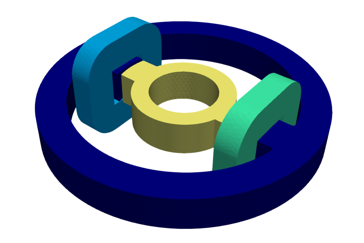
The TEAM problem 24 is shown in the figure above. It serves as a benchmark to validate transient 3D non-linear magneto-quasistatic simulations.
MODEL OVERVIEW
The test rig is composed of a rotor and a stator resembling a switched reluctance machine (SRM). The stator and rotor are both made of solid medium-carbon steel and are mounted in a nonmagnetic cage. The rotor is able to rotate around a stainless steel shaft (not shown in the figure). The stator has an axial length 25.4mm and an outer diameter of 209.0mm, resulting in significant 3D end effects due to the small axial length compared to the radial dimension. The stator poles are fitted with 350-turn coils. More details about the model, including the conductivity and BH-characteristics of the steel used for the rotor and stator can be found in [1].
In this experiment, the rotor is locked at 22° relative to the stator. A step voltage of 23.1V is applied to the coils which are connected in series and have a combined resistance of 3.09 Ohm. The resulting torque rise, which would tend to align the stator and rotor poles, is measured, as well as the current flowing through the coils. The resulting magnetic fields are strong enough to saturate the material, introducing non-linear effects that must be accounted for [1].
FEEN’s APPROACH
The goal is to compute the magnetic fields, coil currents, induced eddy currents, and torque, and then compare these results to measured values. FEEN can calculate all mentioned quantities using either the vector potential approach or the T-Omega-method (H-based approach). The results below are calculated using the T-Omega-method on a standard tetrahedral mesh with 1st order elements.
BH-CURVE FITTING
The original BH-curve provided in the benchmark description misses datapoints for small values of H. This leads to an underestimation of the torque compared to the measured results. Therefore, following [3] and [4], we use a Frohlich-type model to extrapolate the BH-curve for small H values: $$B = \frac{H}{\alpha + \beta |H|}$$.
RESULTS
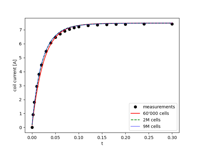
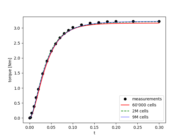
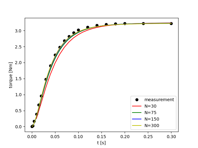
The figures below show the calculated coil currents and the torque compared to measurements.
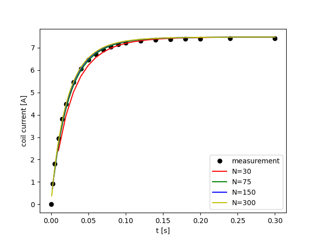
In each case, a convergence study was carried out with regard to the spatial (mesh size) and temporal resolution (number of time-steps). The studies show excellent agreement between the converged results and the experimental measurements, validating FEEN’s ability to accurately simulate electrical machines such as the switched reluctance machine (SRM) presented here.
Computed coil current and torque depending on mesh size compared to measured values:
Computed coil current and torque depending on number of time steps compared to measured values:
PERFORMANCE
REFRENCES
[2] D.Rodger, N.Allen, H.C.Lai, and P.J.Leonard. Calculation of Transient 3D Eddy Currents in Nonlinear Media – Verification Using a Rotational Test Rig“. IEEE Tran. Mag., 30(5), pp.2988-2991, 1994.
[3] https://www.3ds.com/products-services/simulia/resources/team-24-in-opera/
[4] https://www.tailsit.com/publications/team24.pdf